Synthesis Methods
We aim to formulate a transfer function for the filter:
\(H_{Num}(Z)=\sum_{k=0}^{p}{a_kZ^{-k}\ \ }\) (8)
Alternatively, the recurrence defines what is equivalent.
\(y\left(n\right)=\sum_{k=0}^{p}{a_k\ x\left(n-k\right)\ \ }\) (9)
However, as observed for an FIR filter : \(a_k=h(k)\) , the h(n) is the impulse response of the filter. Therefore, the challenge boils down to determining the impulse response h(n) of the digital filter.
Two cases can arise :
We know how to calculate the impulse response \(g(t)\) of the prototype analogue filter (temporal sampling technique).
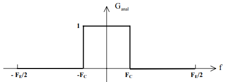
We do not know how to calculate \(g(t)\) , but we know the shape of the frequency response of the prototype analogue filter. \(G_{anal}(j\omega)\) is known, or at least a template (frequency sampling technique).
We will work on an example to implement these two techniques: We aim to generate in digital form an ideal low-pass filter with a cutoff frequency \(F_c=\frac{F_e}{10}\) .